Table of Contents
This is an entry level mini course that takes you through a series of IC related reverse engineering / security tasks. You will practice decapping some samples and then use them in later sections to execute attacks and try other techniques. There are options for both chemical based on chemical free decap/security analysis.
Suggested equipment:
- Temperature controlled heat gun
- Ex: Steinel HG3002LCD
- Propane torch
- Hot plate
- Ex: Thermolyne 1000
- Inspection microscope
- Ex: AmScope SM-4TZ-56S
- Metallurgical microscope
- Ideally with long working distance objectives so they can easily see inside a package
- Ex: Olympus BH2 w/ Mitutoyo M Plan Apo 20x
- Nail polish
- Red of course!
- UV eraser
- Ex: Spectroline PE-140T
- Device programmer
- Ex ideally: BP Microsystems BP-1410 (USB) or BP-1200 (parallel port)
- Checks continuity and power on many chips
- Alternatively: TL866CS
- USB, inexpensive, but limited error checking
Consumables:
- White fuming nitric acid (WFNA)
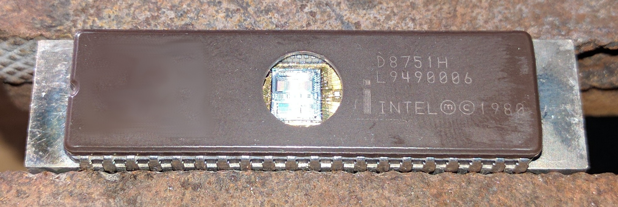
- Intel D8751H (glass frit)
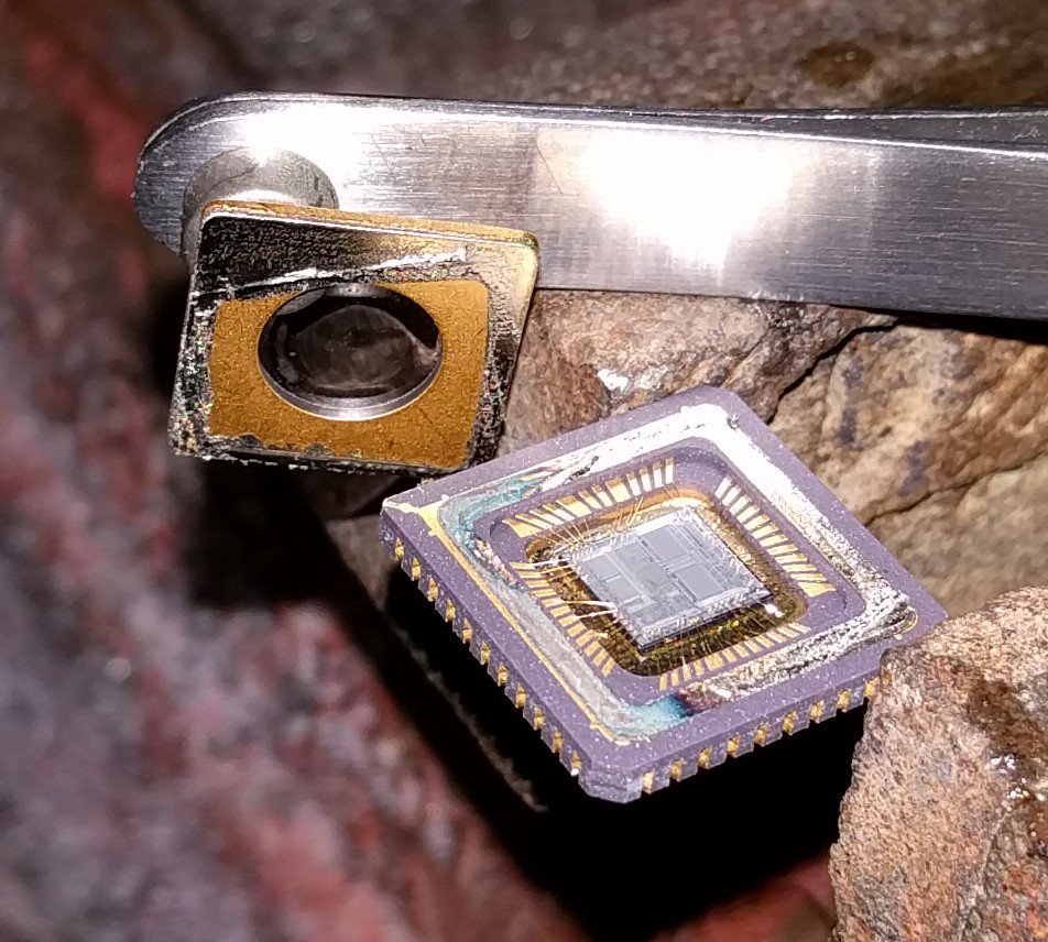
- Intel C8751 (brazed)
- Microchip PIC16C57
- Microchip PIC16F558
Other:
- Some python scripts to generate chip test patterns can be found here
- TODO: pre-generate patterns
Things to add:
- Staining
- Microscope imaging techniques
- rompar
Chip background
8751
Bond wires: usually aluminum
No direct way to verify security set. Secure reads as FF
IIRC BP does not continuity check
These labs were written with 8751H in mind, although other 8751 variations should also work
Microchip PIC16C57
PDIP bond wires: gold
These can also be bought as CDIPs for development
This lab was written with PIC16C57 in mind, although PIC16C57C may work just as well
Microchip PIC16F558
Die photo: TODO grab from flylogic blog
Bond wires: copper
Unit 1: decapsulation
U1L1: CERDIP glass frit
- Select an Intel D8751H (glass frit)
- If necessary, UV erase
- Program with a counting test pattern
- Decap using procedure here
- Readback
- If applicable: verify no continuity errors
- Verify expected pattern
U1L2: CERDIP brazed
- Select an Intel C8751 (brazed lid)
- If necessary, UV erase
- Program with a counting test pattern
- Decap using procedure here
- Readback
- If applicable: verify no continuity errors
- Verify expected pattern
U1L3: PDIP gold bond
- Select a Microchip PIC16C57/P (PDIP)
- Program with a counting test pattern
- Note: “OTP” device (can be UV erased after decap)
- Decap using procedure here
- Readback
- If applicable: verify no continuity errors
- Verify expected pattern
U1L4: PDIP copper bond
- Select a Microchip PIC16F558
- Program with a counting test pattern
- Decap using procedure here
- Readback
- If applicable: verify no continuity errors
- Verify expected pattern
Unit 2: UV attacks
U2L1: basic UV attack
- Select either of the following:
- Microchip PIC16C57
- May be easier as it directly reports security status
- Intel 8751
- If needed, look at the solution below and then use the other as practice
- If not already done so, decap the chip
- Quick security evaluation
- Program with all 0's and secure it
- UV erase the chip (30 min?)
- Verify that the chip is no longer secure and is filled with FF
- This means the chip should be trivially UV attackable
- Put the die under a microscope (inspection is fine) and identify the EPROM and SRAM regions
- SRAM has a rougher texture
- EPROM has a smoother texture
- Use techniques from this page to only mask the EPROM area
- TODO: this page needs polishing / cleanup
- UV erase for 30 minutes
- Readback pattern
- Verify security fuse is clear
- If not, use acetone to clean mask and try again
- Verify pattern was not corrupted
- If it is, consider making the mask larger
Extra credit: no corruption
- Use a pattern of all 0's and secure the device
- Execute above attack
- Read back the device
- Verify device still shows all 0's
Extra credit: find the fuse
- Experiment with different masks outside of the EPROM area to narrow down the fuse location
- Alternatively, look at the fuse under a microscope
Solutions:
U2L2: angled UV attack
- Select either of the following:
- Microchip PIC18F1320
- Classic choice
- Microchip PIC16C74
- Quick security evaluation
- Program with all 0's and secure it
- UV erase the chip for 60 min
- Observe chip status. It should still be secure or maybe even bricked
- Place a chip at a 30 degree angle
- UV erase for 60 min
- Check security status
- If security fuse is not clear, try adjusting angle and re-erasing
Extra credit: dump the firmware
- Do above, but apply masks
- Verify no bits are erased despite erasing at an angle
Solutions:
U2L3: flash UV attack
TODO: what would be a good choice here?
Unit 3: optical glitching
U3L1: static glitch
- Select either of the following:
- Microchip PIC16F84
- Microchip 87C51I or 87C51FAD
- PIC16F84 probably easier as 87C51 doesn't directly indicate protection status
- Select laser
- Green 5 mW laser pointer will likely work well
- Put programmer in a read loop
- Ex: using Linux minipro command line
- Shine randomly across the die and observe responses
- You should see the read result get corrupted sometime
- You will possibly see a firmware dump, but don't expect it
- Put programmer under microscope
- Aim laser pointer at exposed die using helping hands or similar
- WARNING: do not look into microscope
- Use a camera to observe laser
- Slowly move chip around (using hands or XY stage) and observe responses as you move it around
- Scan across the chip until you find a vulnerable area
Extra credit: automated XY scan
- Use a motorized XY scan to read out all chip locations and automatically find vulnerable locations
- Sample workflow using LinuxCNC
Solutions
U3L2: dynamic glitch
Unit 4: power glitching
Unit 5: microprobing
Start with basic probing in U3L1. Then find a way to remove passivation:
- Use a microscope laser if you have one
- Use chemical etching if you can
U3L1: pads
Probe pads / bond wires to get basic familiarity with your probe
TODO: is there a well known device we could activate a debug port on?
U3L2: laser remove passivation
Professional / recommended solution but may not be accessible to all students
U3L3: HF remove passivation
Untested, but I think I can make this work
U3L4: scratch remove passivation
Use needle to scratch off passivation as noted by…Sergei I think?
U3L5: ultrasonic remove passivation
If you have one or maybe build one


