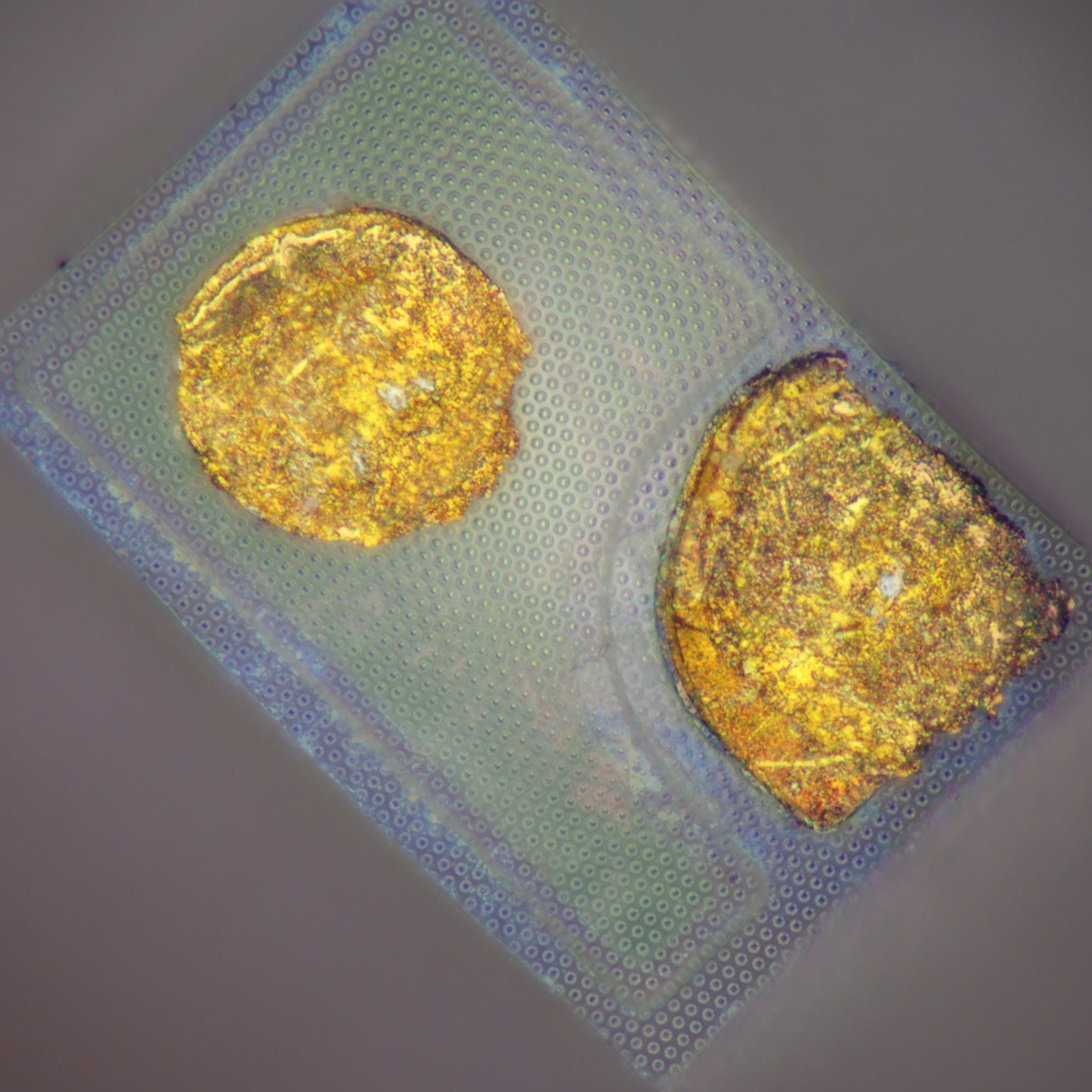
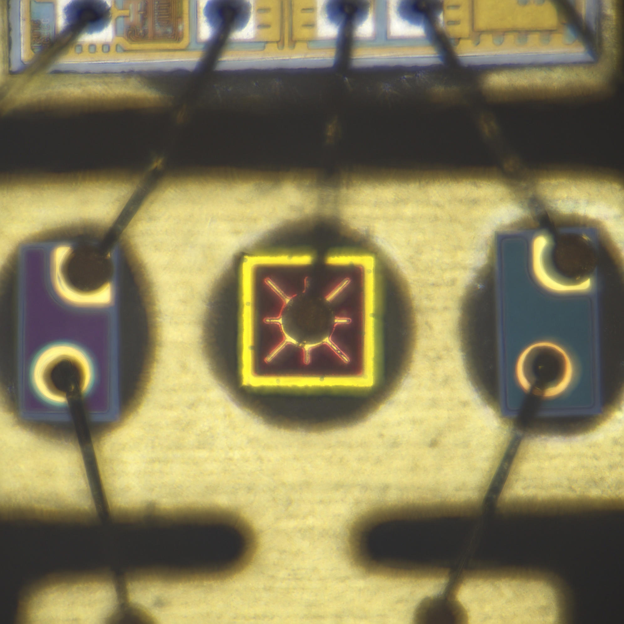
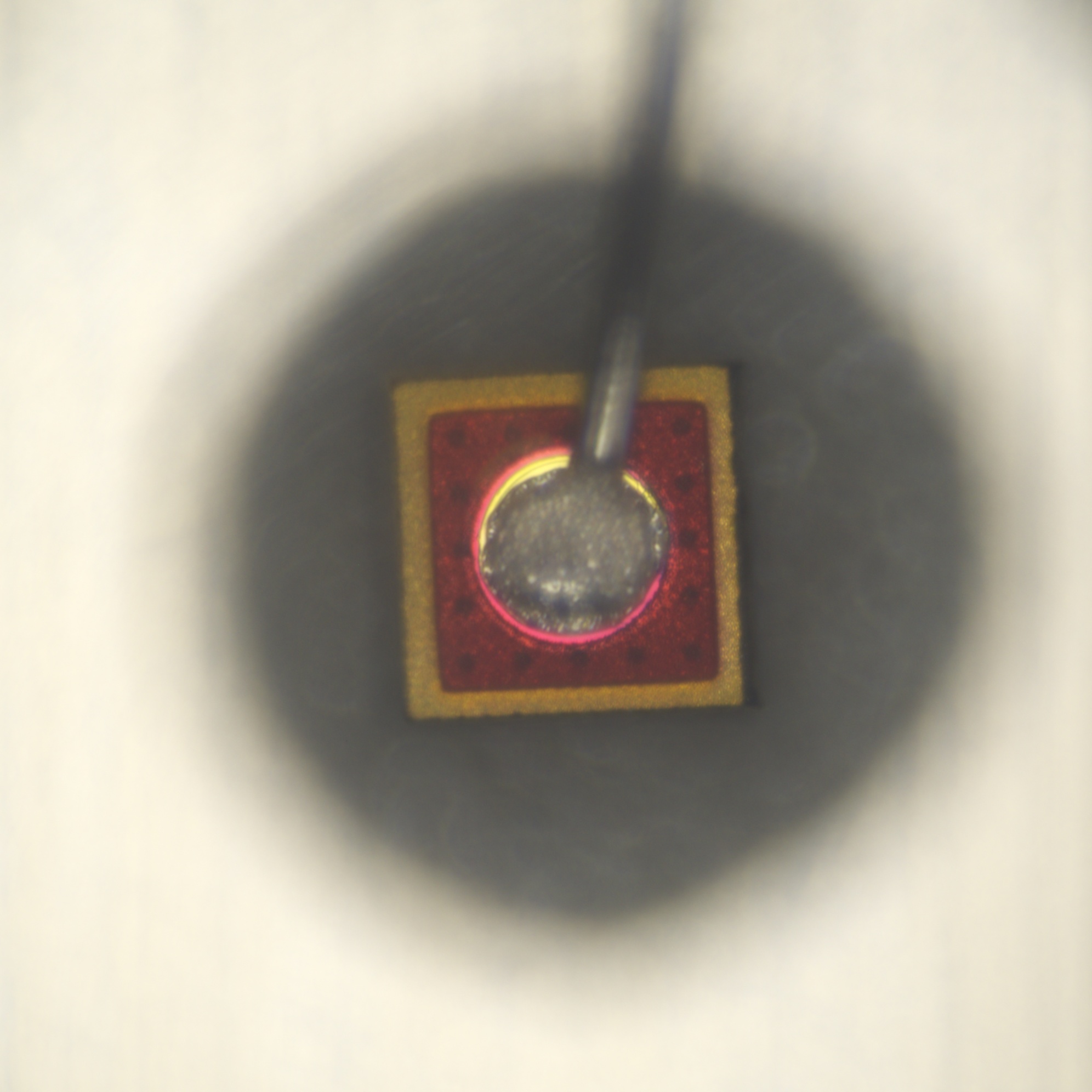
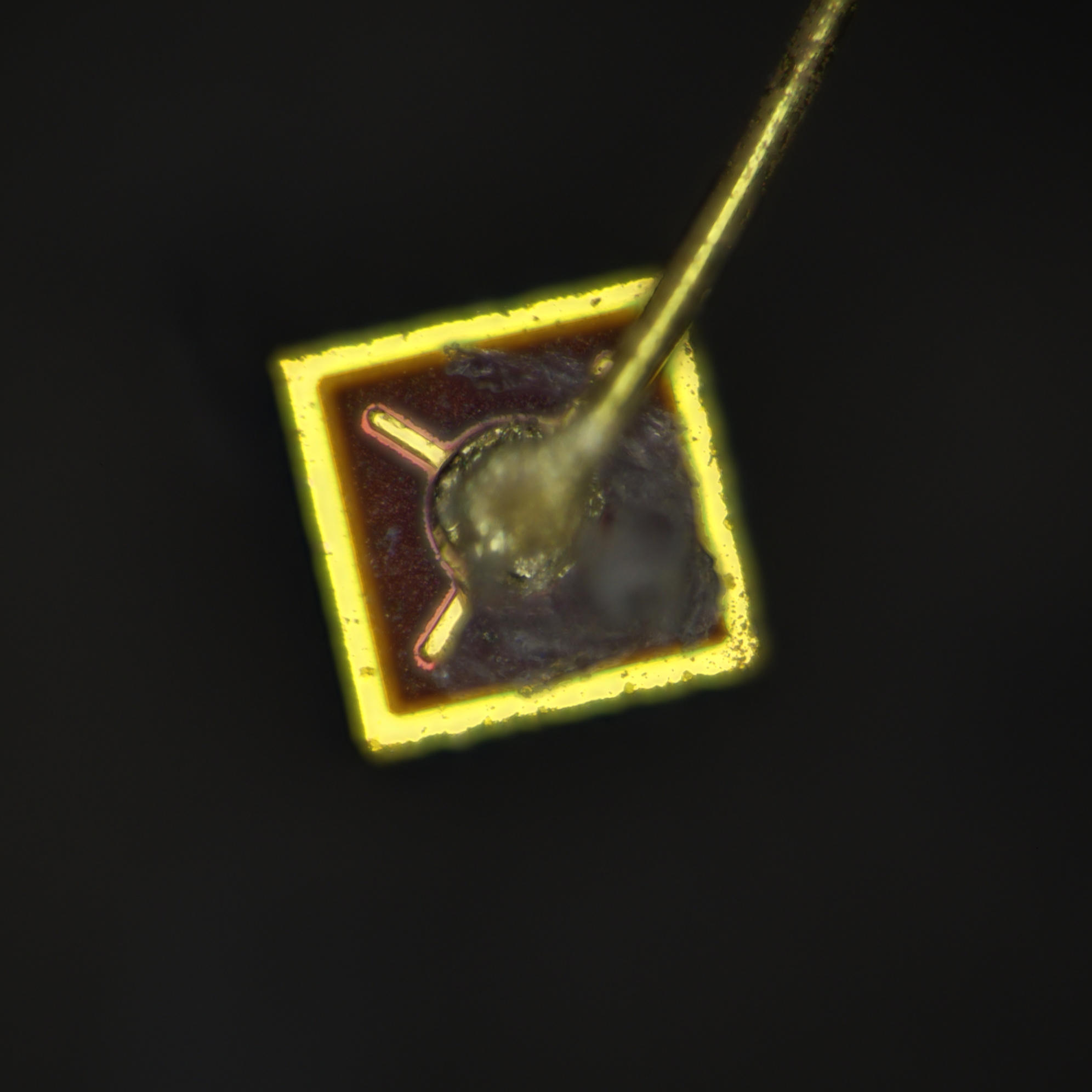
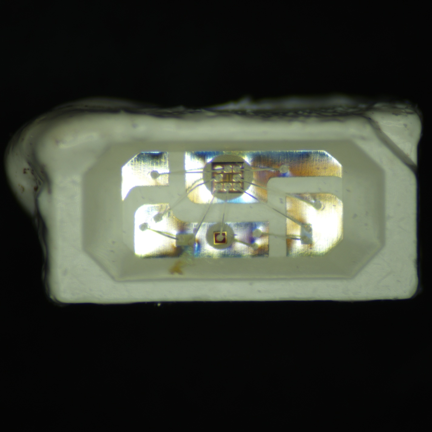
LED
https://www.youtube.com/watch?v=a2IY89FAjZE
https://www.richis-lab.de/Opto03.htm
https://www.richis-lab.de/Opto06.htm
https://www.eevblog.com/forum/projects/optoelectronics-die-pictures/
Open questions:
- Why do red LEDs look so different than green / blue?
- DONE, see below
- Size comparison in various modules?
- WIP below
- Wire bonding unusual? Doesn't look like ball or bond
- Its standard ball bonding, except the ball is on the controller. Wedge was terminated on the LED instead of the package
- What is the hexfet like pattern?
| Vendor | Product | Output | Die area (k um2, m mm2)) | Notes |
|---|---|---|---|---|
| btf-ws2812b | Green | 39.4 | btf-ws2812b | |
| btf-ws2812b | Red | 19.6 | btf-ws2812b | |
| btf-ws2812b | Blue | 33.6 | btf-ws2812b | |
| lampwin-led-12v | Red | 28.0 | lampwin-led-12v | |
| apa102c | Blue | 36.8 | apa102c |
“Red is usually some kind of GaAs and so a vertical structure. Green and blue are GaN and so more lateral. Ok, not really lateral but the substrate is not conducting…”
Red LED
Imaging
Notes:
- Coverslip (with oil, not water) made images much better for packaged LEDs with rough surface (see apa102-2020)
- Infrared produced better images than optical for milky fill (see apa102c)
Except where otherwise noted, content on this wiki is licensed under the following license: CC Attribution 4.0 International
