1. 1 GENERAL INFORMATION
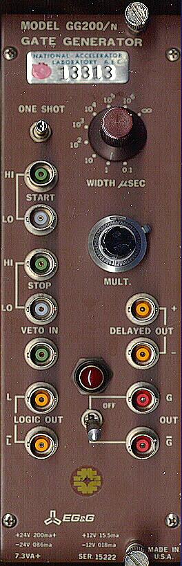
The GG200 GATE GENERATOR (Fig. 1) provides
gating (on-off control) signals for certain M100 System Modules, and provides
versatile timing signals for system use. Six outputs are provided:
system logic and gate signals and their complements, and delayed positive
and negative trigger signals at the end of each gating cycle. The
width of the gate and logic signals is adjustable from 100 nSec to 11 Sec
in eight overlapping ranges, and the width is virtually unaffected by duty-factor
variations. The GG200 timing cycle may be started and stopped by
either logic signals or high-level signals. Output gate and logic
signals may be vetoed (notched) by logic signals. All outputs will
drive 50-ohm loads and are fully protected from overload. A front-panel
lamp indicates both normal operation and overload.
1. 2 SPECIFICATIONS
 HI START:                Direct-coupled.  Accepts signals in the range
                          +/- 5 to +/- 50V.  Input impedance 5. 6K.  Minimum                         width, 100 nSec at +/- 5V; maximum width at +/- 5V
                          must be less than output width for proper
                          operation.  Will sustain +/- 35Vdc or +/-200V                         transients without damage.
 LO START:                Accepts logic signals.  * Input impedance 50 ohms.
                          Minimum width 3. 0 nSec at -600 mv; no maximum
                          width limitation.  Will sustain +/- 3. 5 V dc
                          without damage.
* Compatible with NIM standard fast logic signal definition. T01
denotes ZERO to ONE transition; T10 denotes ONE to ZERO transition.
T01 and T10 measured between -100 mV and -600 mV.
 HI STOP:                 Direct-coupled.  Accepts signals in the range
                          +/-5 to +/-50V.  Input impedance 5.6K.  Minimum
                          width, 100 nSec at +/- 5V.  HI STOP input acts to
                          inhibit START; HI STOP signal should end
                          before next START.  Will sustain +/- 35V dc or
                          +/- 200V transients without damage.

 LO STOP:                 Direct-coupled.  Accepts logic signals. * Input
                          impedance 50 ohms.  Minimum width, 10 nSec
                          at -600mV.  LO STOP input can inhibit START;
                          LO STOP signal should end before next START.
                          Will sustain +/- 3. 5V dc without damage.

 VETO IN:                 Direct-coupled.  Accepts logic signals. * Input
                          impedance 50 ohms.  Will sustain +/- 5. 0 V dc
                          or +/- 100V fast transients without damage.
                          VETO IN vetoes LOGIC and GATE OUTPUTS
                          without affecting START, STOP or timing cycle.
 LOGIC OUT (L):           Logic signals * on 50-ohm termination.  Typical
                          T01 2.5 nSec, T10 2.5 nSec.

 LOGIC OUT                Complementary logic signals * on 50-ohm
                          termination.  Typical T10 2. 5 nSec, To, 2. 5 nSec.
 G OUT (50-ohm load):     Quiescent level 0 to +0.5V; pulsed level 13. 5+/-
                          1.0V.  Typical 1. 0 to 10V Tr 50 nSec; typical
                          10 to 1.0V Tf 50 nSec.
 G OUT (Hi-Z load):       Quiescent level 0 to +0. 5V; pulsed level 14.  0
                          +/- 1.0V.  Typical 1. 0 to 10V Tr 50 nSec; typical
                          10 to 1.0V Tf 50 nSec.
* Compatible with NIM standard fast logic signal definition.
T01 denotes ZERO to ONE transition; T10 denotes ONE to ZERO transition.
T01 and T10 measured between -100 mV and -600 mV.
G OUT (50-ohm load):      Quiescent level 13.0 +/- 1.0 volts; pulsed level
                          0 to +0. 5 volt.  Typical 10 to 1.0 volt Tr
                          60  nSec; typical 1.0 to 10 volt Tf  80 nSec.
G OUT (HI-Z load):        Quiescent level 14.0 +/- 1.0 volts; pulsed level
                          0 to +0.5 volt.  Typical 10 to 1.0 volt Tr
                          60 nSec; typical 1.0 to 1O volt Tf 80 nSec.
 G OUT AND G' OUT         Internal current limit to approximately 300 ma;
 PROTECTION:              reverse current limiter, approximately 150 ma,
                          protects against back-feeding from external
                          positive voltage sources.
 DELAYED OUT              Positive 18-ma current pulse (900 mv into
                          50 ohms).  Typical 10% - 90% Tr 4 nSec, Tf 13
                          nSec.  Pulse begins at GATE OUT trailing edge;
                          width indicates GG200 internal reset time.
                          Typical widths as follows:
                          RANGE                    WIDTH
                          0. 1, 1. 0               70 nSec
                          10, 10  2                 1 uSec
                          103,  104                95 uSec
                          105,  106               9. 5 mSec
 DELAYED OUT              Negative  14-ma current pulse (-700 mv into
                          50 ohms).  Same width and time relationships
                          as DELAYED OUT (+) pulse.  Typical Tr 4 nSec,
                          Tf 4 nSec.
 WIDTH RANGE:             100 nSec to 11 sec in eight decades with 1.0 to
                          11 ten-turn multiplier.  Additional position for
                          latching operation.
 WIDTH CAL:*             +/- 10% of full scale, 100 nSec to 11 sec. +/- 5%
                         of full scale, 1 uSec to 1. 1 sec.
 WIDTH STABILITY:*       +/-O. 05%/degC' on 0.1 and 1 uSec ranges.

 WIDTH JITTER:*          Less than +/-O. 5% (measured at 500 nSec) with
                         random input of duty factor approaching 100%.

 TYPICAL DELAY:*         START to LOGIC OUT, 13 nSec.
                         STOP  to LOGIC OUT, 16 nSec.
                         VETO to LOGIC OUT, 4 nSec.
 POWER
 REQUIREMENTS:           +20V,  91  ma.
                         +10V,  16  ma.
                         -10V,  28  ma.
                         -20V,  76  ma.
                         +20V NP**, 120 ma plus load requirement.
                         -20V NP**,  14 ma plus load requirement.

 PANEL COLOR:             Gold.

 * - Measure at LOGIC OUT connector.

** - Non-Premium.
|
 |
Up
to a higher level directory |
| For
more information
