The CC-A1 Crate Controller is designed to meet the latest specifications promulgated by ESONE Document 4600e (March 1972). The new specifications allow the CC-A1 to be used in the most advanced CAMAC systems, while preserving its compatibility with older CAMAC systems which require only the type A. In addition to complying with the new Type A-1 specifications, the controller has the fol- lowing special features:
 - Better than 4600e spec branch highway re-
 ceivers and drivers.
 - Branch Command signals latched and
 stored in registers for high noise immunity
 operation.
 -Controller will not come "on line" if ano-
 ther controller on branch highway is using
 the same crate address and will indicate
 error with a "Warn: BCR OCC" lamp.
 - BX and X (command accepted) lines prop-
 erly utilized.
 - Dataway P2 line may be used as command
 sequence "Hold" with the installation of a
 jumper wire thus allowing "handshake"
 delay of dataway timing.
 - BSC-BSC(R) lines may be jumpered to
 module return bus by the installation of a
 jumper wire.
 - Crate Address may be changed without re-
 moving module completely from crate.
 -All important switches and indicators are
 placed in the most clearly visible and read-
 ily accessable area between the Branch
 Highway connectors.
 - GL lines multiplexed separately with the
 READ lines to prevent ambiguity and false
 information.
 CCT-Al
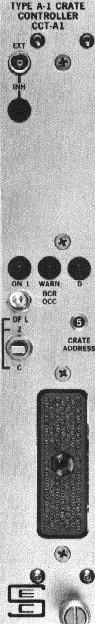
This module incorporates a complete Branch Highway terminator within the unit, elimi- nating the need for a Separate Branch High- way Terminator and cable. This module is used primarily in single crate systems or in the last crate of a multi-crate system.
DESCRIPTION
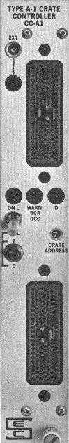
The CC-A1 Crate Controller is a double width CAMAC module which interfaces the branch highway signals to the crate dataway. All other modules in the crate are controlled by the crate controller via signals on the dataway; the crate controller occupies the two far right stations in the crate. Mounted on the front panel of the crate controller are two branch highway port connectors which allow the crate con- troller to be interconnected to the branch highway with up to six other crate controllers; at the rear of the crate controller, printed circuit card connectors plug into the dataway sockets when the module is inserted in the crate. Each crate has an address (1-7) which is selected by a rotary switch accessible only with the crate controller partially (approximately 1") removed from the crate. The selected address is indicated on the front panel during both power on and off conditions. "I" and On Line ("ON L") conditions are visually indicated by means of LEDs on the front panel. A "WARN: BCR OCC" LED indicates a crate address occupied condition by slow blink (approximately 2 per sec). A "D" LED indicates the presence of a demand operation.
OPERATION
A crate controller which is connected to the branch highway will not interfere with branch highway operations if the power to the crate is off, or if the crate controller is switched off line. A crate controller which is connected and switched on line will respond as directed by the Branch Highway Driver. The Branch Initialize signal (BZ) takes precedence over all other branch signals, and will initialize the crate controller and crate modules. When the crate controller is correctly addres- sed (the branch address signals (BCR) on the line selected by the crate address switch in the controller) the crate con- troller will accept branch highway commands. The command sequence generally involves the following:
 -the branch timing signal (BTA)
 -the decoding of branch Station Number signals (BN) to
 dataway crate Station Numbers (N)
 -the duplication of the branch Address (BA) and Function
 (BF) signals on the dataway Address (A) and Function (F)
 lines
 -the transfer of information to or from the branch Read-
 Write lines (BRW) to the dataway Write lines (W) or from
 the dataway Read lines (R)
 -the generation by the crate controller of the response
 branch timing signal (BTB)
 -and the generation by the crate controller of the dataway
 timing signals Busy (B) and Strobes S1 and S2.
Also, the crate controller can impliment several specialized commands.
Another mode of operation performed by the crate controller is the Graded L sequence which is a systematic inspection of the modules in the crate in order to determine which may re- quire attention. The Graded L sequence may be initiated by a
Look-At-Me signal (L) from a module in the crate, or by a branch Graded L signal (BG).
Other details of the TYPE A-1 Crate Controller specifications and operations are in ESONE Document 4600e (rev.).
|
Action |
Command |
Response |
||
|
N |
A |
F |
||
Generate Dataway Z Generate dataway C Read GL Load SNR Remove dataway I Set dataway I Test dataway I Disable BD output Enable BD output Test BD output enabled Test demands present |
28 28 30 30 30 30 30 30 30 30 30 |
8 9 0-7 8 9 9 9 10 10 10 11 |
26 26 0 16 24 26 27 24 26 27 27 |
BQ=0 BQ=0 BQ=1 BQ=1 BQ=0 BQ=0 BQ=1 if I=1 BQ=0 BQ=0 BQ=1 if BD enabled BQ=1 if demands present |
|
N Code |
Use |
B, S1, S2 |
N(0) N(1)-(23) N(24) N(26) N(28) N(30) N(25,27,29,31) |
Reserved Address the corresponding normal station Address preselected normal stations Address all normal stations Address crate controller only Address crate controller only Reserved |
Yes
Yes
Yes
Yes
No
|